I have been solutioning on OCI since the general availability of generation 2 (what was BareMetal cloud). It has been rare, for me, to implement Fast Connects with cross connection. DRCC is definitely going to be presenting more cross connect opportunities.
Customers that choose a data center provider for the DRCC implementation will be required to setup cross connections, generate letters of authorization for the cabling and ensure that they account for no single points of failure.
The customers network switches will help to drive the final design. Customers could have switches that support LACP, MLAG or even stacking.
- LACP allows network devices to bundle multiple physical links into a single logical link, creating a Link Aggregation Group (LAG). This bundling increases bandwidth, provides link redundancy, and enables load balancing across the aggregated links.
- MLAG, or multi-chassis link aggregation, is the use of multiple physical switches to create one single logical switch (in the case of Cisco they would use EtherChannel between the two physical switches).
- Stacking uses a control plane to combine multiple physical switches into one logical switch.
A couple of things to keep in mind here are as follows:
- By default, OCI Compute instances use an MTU of 9000 bytes (Jumbo Frames)
- While LAG bundles multiple ports together, the packets being transmitted are not broken into the multiple ports (i.e. a transmitted packet can only be transmitted over one of the ports defined in the LAG)
In addition to the customer switch capabilities (LACP, MLAG, Stacking, EtherChannel, etc) the network support team standards also play into the final design. Just because the switches have the capability to create logical interfaces does not mean that the network team is inclined to implement them and support them.
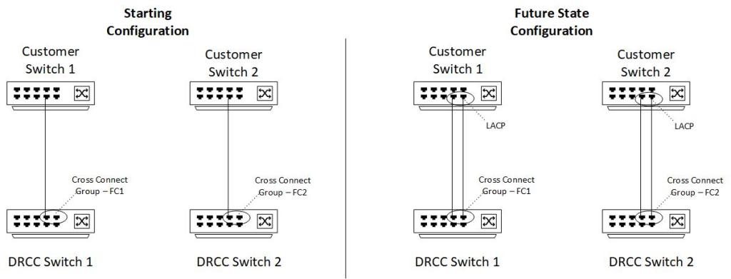
LACP is generally limited to ports on a singular switch. A design using LACP could have one Fast Connect mapped to OCI DRCC physical switch 1 to customer switch 1. While Fast Connect 2 would be mapped to OCI DRCC physical switch 2. The beauty of this solution allows the customer to create a cross connect group within the Fast Connect.
The cross connect group can be initiated with just one cross connection to start. This allows the customer the ability to add future cross connections as bandwidth and redundancy are required. As an example, a customer may start with 1 by 1Gb ports in the cross connect group. The customer could add another 1Gb port to the cross connect group and would effectively have 2Gb of bandwidth.
The image below represents an LACP co-location configuration:
An mLAG configuration may look like the following:
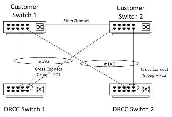
I have had been on projects that have declined to use LACP and opted for a full mesh configuration of Fast Connect. A full mesh configuration would look like the following:

One a side note, it is comforting to know that if a cross connection is accidentally deleted, a Service Request can be submitted and routed to the Fast Connect support group to recover the cross connections. You will need the original letters of authorization but this prevents having to cable new ports should a cross connect need to be recovered.
This blog does not go into the details of bandwidth design, routing, firewalls, etc. This was meant to solely focus on the physical connectivity options for a co-location DRCC. The key things to remember in any of the above configurations is to ensure that there is connectivity to both of the DRCC switches. After creating the first Fast Connect, use the specify router proximity configuration field when creating another Fast Connect. Verify that both of the DRCC switches are correct in the generated letters of authorization.
